
ASTM D3840-24 “玻璃纤维”(玻璃纤维增强热固性树脂)非承压管道管件标准规范

VIP免费

Designation: D3840 −24
Standard Specification for
“Fiberglass” (Glass-Fiber-Reinforced Thermosetting-Resin)
Pipe Fittings for Nonpressure Applications
1
This standard is issued under the fixed designation D3840; the number immediately following the designation indicates the year of
original adoption or, in the case of revision, the year of last revision. A number in parentheses indicates the year of last reapproval. A
superscript epsilon (´) indicates an editorial change since the last revision or reapproval.
1. Scope*
1.1 This specification covers fiberglass pipe fittings in-
tended for use in gravity flow systems for conveying sanitary
sewage, storm water, and those industrial wastes for which the
fittings are determined to be suitable. Elbows, tees, laterals,
crosses, reducers, and adapters are included. Both glass-fiber-
reinforced thermosetting-resin pipe (RTRP) and glass-fiber-
reinforced polymer mortar pipe (RPMP) are fiberglass pipes.
NOTE 1—For the purposes of this standard, polymer does not include
natural polymers.
1.2 This specification is intended to cover only dimensions,
material properties, and workmanship rather than the structural
design of the fittings. The structural design of the fittings shall
be as agreed upon between purchaser and supplier, and needs
to take into consideration the anticipated conditions of instal-
lation and service.
1.3 This specification covers only fittings fabricated from
cut sections of pipe, or from a combination of pipe sections and
contact molded (hand layup), or machine fabricated compo-
nents.
1.4 The values stated in inch-pound units are to be regarded
as the standard. The values given in parentheses are provided
for information purposes only.
1.5 The following safety hazards caveat pertains only to the
test method portion, Section 11, of this specification. This
standard does not purport to address all of the safety concerns,
if any, associated with its use. It is the responsibility of the user
of this standard to establish appropriate safety, health, and
environmental practices and determine the applicability of
regulatory limitations prior to use.
NOTE 2—There is no known ISO equivalent to this standard.
1.6 This international standard was developed in accor-
dance with internationally recognized principles on standard-
ization established in the Decision on Principles for the
Development of International Standards, Guides and Recom-
mendations issued by the World Trade Organization Technical
Barriers to Trade (TBT) Committee.
2. Referenced Documents
2.1 ASTM Standards:
2
D638 Test Method for Tensile Properties of Plastics
D883 Terminology Relating to Plastics
D1600 Terminology for Abbreviated Terms Relating to Plas-
tics (Withdrawn 2024)
3
D1763 Specification for Epoxy Resins
D2290 Test Method for Apparent Hoop Tensile Strength of
Plastic or Reinforced Plastic Pipe
D3262 Specification for “Fiberglass” (Glass-Fiber-
Reinforced Thermosetting-Resin) Sewer Pipe
D3567 Practice for Determining Dimensions of “Fiberglass”
(Glass-Fiber-Reinforced Thermosetting Resin) Pipe and
Fittings
D3892 Practice for Packaging/Packing of Plastics
F412 Terminology Relating to Plastic Piping Systems
F477 Specification for Elastomeric Seals (Gaskets) for Join-
ing Plastic Pipe
3. Terminology
3.1 Definitions:
3.1.1 General—Definitions are in accordance with Termi-
nologies D883 and F412. Abbreviations are in accordance with
Terminology D1600, unless otherwise indicated.
3.2 Definitions of Terms Specific to This Standard:
3.2.1 fiberglass pipe, n—a tubular product containing glass
fiber reinforcements embedded in or surrounded by cured
thermosetting resin.
3.2.1.1 Discussion—It is acceptable for the composite struc-
ture to contain aggregate, granular or platelet fillers, thixotropic
agents, pigments or dyes. It is acceptable to include thermo-
plastic or thermosetting liners or coatings.
1
This specification is under the jurisdiction of ASTM Committee D20 on
Plastics and is the direct responsibility of Subcommittee D20.23 on Reinforced
Thermosetting Resin Piping Systems and Chemical Equipment.
Current edition approved Aug. 1, 2024. Published August 2024. Originally
approved in 1979. Last previous edition approved in 2019 as D3840 – 19. DOI:
10.1520/D3840-24.
2
For referenced ASTM standards, visit the ASTM website, www.astm.org, or
contact ASTM Customer Service at www.astm.org/contact. For Annual Book of
ASTM Standards volume information, refer to the standard’s Document Summary
page on the ASTM website.
3
The last approved version of this historical standard is referenced on
www.astm.org.
*A Summary of Changes section appears at the end of this standard
Copyright © ASTM International, 100 Barr Harbor Drive, PO Box C700, West Conshohocken, PA 19428-2959. United States
This international standard was developed in accordance with internationally recognized principles on standardization established in the Decision on Principles for the
Development of International Standards, Guides and Recommendations issued by the World Trade Organization Technical Barriers to Trade (TBT) Committee.
1

3.2.2 reinforced polymer mortar pipe, n—a fiberglass pipe
with aggregate.
3.2.3 reinforced thermosetting resin pipe, n—a fiberglass
pipe without aggregate.
3.2.4 qualification, n—One or more tests used to prove the
design of a product. Not a routine quality control test.
NOTE 3—Qualification requirements appear in 6.1,7.2, and 12.3.
4. Materials
4.1 Laminating Resin:
4.1.1 Type 1—Polyester thermosetting resin, with or without
fillers or thixotropic agents or both.
NOTE 4—For the purpose of this standard, polyester includes vinyl ester
resins.
4.1.2 Type 2—Epoxy resin, conforming to the requirements
of Specification D1763, with or without fillers or thixotropic
agents, or both.
4.2 Reinforcement:
4.2.1 Grade 1—A commercial grade of glass fibers with a
polyester-compatible finish.
4.2.2 Grade 2—A commercial grade of glass fibers with an
epoxy-compatible finish.
4.3 Gaskets—The elastomeric gaskets used with the fittings
joined to pipe shall conform to the requirements of Specifica-
tion F477.
5. Fabrication
5.1 Permissible Components:
5.1.1 Fittings covered under this specification shall be
fabricated from cut section of pipe that conform to the
requirements of Specification D3262, or from a combination of
such pipe sections and contact molded (hand layup) or machine
fabricated components.
5.1.2 It is acceptable to incorporate saddles, wrappers,
necked flanges, and other components of metal or other
dissimilar materials, as agreed upon between purchaser and
supplier, provided the materials of such components are
resistant to the corrosive effects of the internal and external
environments anticipated in service, or are lined or coated or
both with materials that provide equivalent protection.
5.2 Bonding and Laminate Overlay Reinforcements:
5.2.1 Sections of the fitting shall be aligned and bonded
together using polyester (Type 1) or epoxy (Type 2) resin
materials with or without fiberglass reinforcement. Fiberglass
reinforcement materials shall be compatible with the laminat-
ing resin; Grade 1 reinforcements shall be used with Type 1
laminating resin, and Grade 2 reinforcements shall be used
with Type 2 laminating resin.
5.2.2 It is acceptable to apply laminated reinforcing over-
lays of bonded seams to either the outside or inside surface of
the fitting, or to both inside and outside surfaces. The laminate
shall be of chemically resistant construction suitable for the
purpose and shall provide the additional strength necessary to
meet the physical requirements shown in Table 1. Finished
seam overlays shall be built up in two or more successive
layers of reinforcement and shall be as crevice free as
described in this paragraph and 5.2.3. The width of the first
layer shall be 2 in. (50 mm) minimum. Successive layers shall
increase uniformly in width to provide the specified minimum
total width of overlay that shall be centered on the seam.
Alternatively, it is permissible for the first layer to be the
widest with successive layers decreasing uniformly in width
centered on the seam. Width of the last layer shall be 2 in. (50
mm) minimum. Table 1 shows minimum total widths of
overlays required. The ends of each layer of reinforcement
shall be overlapped a minimum of 1 in. (25 mm). Crevices
between joined sections shall be filled with a filled resin paste,
leaving a smooth inner surface. The interior of the seams shall
also be sealed by covering with not less than a 0.03 in. (0.76
mm) thickness of reinforced resin-rich surface that provides
corrosion resistance suitable for the intended service.
Alternatively, when it is necessary to fabricate a fitting where
the size and configuration do not allow adequate access to
interior seams, the cut edges of sections shall be sealed prior to
assembly and any reinforcing overlay protected by a resin-rich
surface that provides corrosion resistance suitable for the
intended service.
5.2.3 Components of dissimilar materials, such as steel to
polyester or epoxy laminates, or polyester to epoxy laminates,
shall be bonded with a resin compound capable of adhering to
both materials. The resin compound shall contact the joining
surfaces of both components with the spaces between the
components filled. The excess resin compound that extrudes
from the seam shall be removed, leaving a smooth fillet.
Sealing laminates and reinforcing overlays shall be applied
where required (see 5.1.1,5.2.1, and 5.2.2).
6. Joints
6.1 The fitting joints shall be coupling or bell-and-spigot in
accordance with the joint requirements of Specification D3262,
unless otherwise specified. It is acceptable to qualify joint
designs on straight sections of pipe.
7. Physical Requirements
7.1 Properties of structural laminates, used either as seam
reinforcing overlays or as contact molded or machine fabri-
cated components, other than cut sections of pipe, shall be as
shown in Table 1, when tested in accordance with 11.1.
7.2 Shear Strength—The minimum shear strength of seam
reinforcing overlays shall be 500 psi (3.45 MPa) when tested in
accordance with 11.2.
8. Dimensions and Permissible Variations
8.1 Wall Thickness—The wall thickness of any area of the
fitting furnished under this specification shall not at any point
be less than 87.5 % of the nominal wall thickness published in
the manufacturers’ literature current at the time of purchase
when measured in accordance with 11.3.1.
8.2 Fitting Diameters—Fittings shall be supplied in nominal
diameters as given in Specification D3262. The fitting diameter
tolerances shall be as given in Specification D3262, when
measured in accordance with 11.3.2 or 11.3.3 as applicable.
8.3 Lengths—The tolerance for the laying length and other
significant dimensions shall be 62 in. (651 mm) or 61 % of
D3840 − 24
2

the dimension, whichever is greater, when measured in accor-
dance with 11.3.4. See Tables 2-6 and Figs. 1 and 2 for typical
minimum laying lengths.
8.4 Angular Dimensions—Angular dimensions shall have a
tolerance of 61° when measured in accordance with 11.3.5.
9. Workmanship, Finish, and Appearance
9.1 The inside surfaces of each fitting shall blend smoothly
and shall be free of bulges, dents, ridges, or other irregularities
that result in a variation of more than
1
⁄
8
in. (3.2 mm) from that
obtained on adjacent portions of the surface.
NOTE 5—This requirement is concerned with roughness and waviness
and does not apply to diameter tolerances or thickness of internal seam
reinforcement if present. See 8.2 for inside diameter tolerances, including
internal reinforcement.
9.2 Joint sealing surfaces shall be free of dents, gouges,
cracks, and other surface imperfections that will affect the
integrity of the joints.
9.3 The inner surface of each reinforced plastic fitting
component and connecting seam shall be composed of resin
with or without reinforcement, aggregate, or filler. No glass
fiber-reinforcement shall penetrate the interior surface of the
fitting wall.
9.4 Internal and external reinforcements shall be free of
voids, dry spots, cracks, and crazing. Some waviness in the
internal reinforcement is permissible so long as the surface is
smooth. Unless otherwise agreed upon between purchaser and
supplier, all fittings shall meet the visual and repair criteria of
Tables 7 and 8.
9.5 Fittings shall show good workmanship, including uni-
formity from item to item.
10. Sampling
10.1 Lot—Unless otherwise agreed upon between purchaser
and supplier, one lot shall consist of 100 fittings of each type,
grade, and construction of laminate overlay reinforcement, or
contact molded or machine fabricated component, or both.
10.2 Unit Sample—Select one fitting from each lot. Prepare
a sample or representative laminate and test specimens to
determine conformance with the requirements of 7.1 for
ultimate tensile strength.
11. Test Methods
11.1 Ultimate Tensile Strength—Determine the ultimate ten-
sile strength of sample laminate specimens cut from seam
reinforcing overlays or contact molded or machine fabricated
TABLE 1 Minimum Properties of Structural Laminates
Nominal Diameter, in. (mm) Minimum Hoop Tensile
Strength, lbf/in. (kN/m) of
width
A
Minimum Axial Tensile
Strength, lbf/in. (kN/m)
of circumference
A
Minimum Total Width of
Overlay, in. (mm)
B
8 (203) 1600 (280) 1600 (280) 4 (100)
10 (254) 1600 (280) 1600 (280) 4 (100)
12 (305) 1600 (280) 1600 (280) 4 (100)
14 (356) 1600 (280) 1600 (280) 4 (100)
15 (381) 1600 (280) 1600 (280) 4 (100)
16 (406) 1600 (280) 1600 (280) 4 (100)
18 (457) 1600 (280) 1600 (280) 4 (100)
20 (508) 1600 (280) 1600 (280) 4 (100)
21 (533) 1600 (280) 1600 (280) 4 (100)
24 (610) 1600 (280) 1600 (280) 4 (100)
27 (686) 1600 (280) 1600 (280) 4 (100)
30 (762) 1600 (280) 1600 (280) 4 (100)
33 (838) 1700 (300) 1700 (300) 6 (150)
36 (914) 1800 (315) 1800 (315) 6 (150)
39 (991) 2000 (350) 2000 (350) 6 (150)
42 (1067) 2100 (368) 2100 (368) 6 (150)
45 (1143) 2300 (403) 2300 (403) 6 (150)
48 (1219) 2400 (420) 2400 (420) 8 (200)
51 (1295) 2600 (455) 2600 (455) 8 (200)
54 (1372) 2700 (473) 2700 (473) 8 (200)
60 (1524) 3000 (525) 3000 (525) 8 (200)
66 (1676) 3300 (578) 3300 (578) 10 (250)
72 (1829) 3600 (630) 3600 (630) 10 (250)
78 (1981) 3900 (683) 3900 (683) 10 (250)
84 (2134) 4200 (736) 4200 (736) 12 (300)
90 (2286) 4500 (788) 4500 (788) 12 (300)
96 (2438) 4800 (841) 4800 (841) 14 (350)
102 (2591) 5100 (893) 5100 (893) 16 (400)
108 (2743) 5400 (946) 5400 (946) 16 (400)
114 (2896) 5700 (998) 5700 (998) 16 (400)
120 (3048) 6000 (1051) 6000 (1051) 16 (400)
132 (3353) 6600 (1156) 6600 (1156) 18 (450)
144 (3658) 7200 (1261) 7200 (1261) 20 (500)
156 (3962) 7800 (1366) 7800 (1366) 22 (550)
A
The values given are minimums only. Sound engineering practice dictates that all fittings be designed to withstand the loads and conditions anticipated in the service for
which they are intended.
B
The dimensions given are minimums for“ butt-and-strap’’ type joints.
D3840 − 24
3

摘要:
展开>>
收起<<
本页面详细介绍ASTM D3840-24标准规范,该标准针对采用玻璃纤维增强热固性树脂制造的非承压管道及管件,适用于埋地或地上排水、排污及工业液体输送系统。内容涵盖材料性能、制造工艺、尺寸公差、物理力学测试及长期使用可靠性要求,帮助工程技术人员、采购方和质检部门准确理解和应用该标准,确保管道系统在无内压工况下的结构完整性、耐腐蚀性与使用寿命,是合规选材与质量验收的重要参考依据。
声明:本文档系会员上传,若文档所含内容侵犯了您的版权或隐私,请立即通知,我们立即给予侵权申诉删除!
相关推荐
-
ISO TR 25901-1-2016 焊接及相关工艺-词汇第1部分:通用术语VIP免费

 2024-09-13 166
 -
ISO IEC Guide 98-3-2008 Suppl.2-2011 测量不确定度第3部分:测量不确定度表达指南 (GUM:1995) 补充 2:扩展到任意数量的输出量VIP免费
 2024-09-15 155
 -
ISO 4413-2010 液压流体动力-系统及其元件的一般规则和安全要求VIP免费
 2025-02-07 147
 -
ISO 965-2-2024 通用公制螺纹 公差 第2部分:内螺纹和外螺纹尺寸极限VIP免费
 2025-03-20 283
 -
ISO 6583-2024 甲醇作为船用燃料 一般要求和规范VIP免费
 2025-04-02 236
 -
ISO 23908-2024 锐器伤害防护 用于血液测试、监测、取样和医疗物质给药的一次性针头、导管引入器和针头的锐器防护机构 要求和试验方法VIP免费
 2025-04-16 152
 -
ISO 14119-2024 机械安全——与防护装置相关的联锁装置——设计和选择原则VIP免费
 2025-04-21 170
 -
ISO 6028-2023 医疗机构管理 流行病应对 自我症状检查应用程序的功能要求VIP免费
 2025-05-18 197
 -
ISO 12233-2024 数字照相机——分辨率和空间频率响应VIP专免
 2025-06-22 200
 -
ISO 14001-2026 环境管理体系 要求和使用指南 高清英文版VIP免费
 2026-04-20 999+
作者:乔大爷开音响
分类:国外协会
价格:14星币
属性:9 页
大小:367.78KB
格式:PDF
时间:2025-05-14
相关内容
-

ISO IEC 19583-27-2025 信息技术 元数据概念与使用 第27部分:可计算数据注册元模型与高通量测序生物信息学分析之间的映射
分类:国际标准
时间:2026-09-10
标签:ISO
格式:PDF
价格:26 星币
-
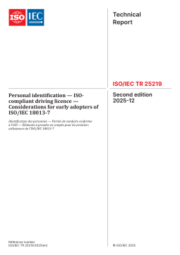
ISO IEC TR 25219-2025 个人识别 — ISO合规驾驶执照 — ISOIEC 18013-7早期采用者需考虑的事项
分类:国际标准
时间:2026-09-10
标签:ISO
格式:PDF
价格:26 星币
-
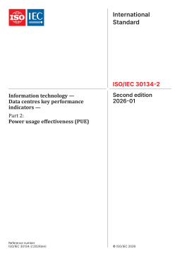
ISO IEC 30134-2-2026 信息技术 — 数据中心关键性能指标 — 第2部分:电能使用效率(PUE)
分类:国际标准
时间:2026-09-10
标签:ISO
格式:PDF
价格:26 星币
-

ISO IEC 30108-1-2026 生物测定 身份属性验证服务 第1部分IAVS服务
分类:国际标准
时间:2026-09-10
标签:ISO
格式:PDF
价格:26 星币
-
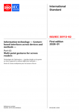
ISO IEC 30113-62-2026 信息技术 跨设备和方法的基于手势的界面 第62部分屏幕阅读器的多点手势
分类:国际标准
时间:2026-09-10
标签:ISO
格式:PDF
价格:26 星币


