
ASTM D4761 - 25 木材及木质结构材料力学性能的标准试验方法

VIP免费

Designation: D4761 −25
Standard Test Methods for
Mechanical Properties of Lumber and Wood-Based
Structural Materials
1
This standard is issued under the fixed designation D4761; the number immediately following the designation indicates the year of
original adoption or, in the case of revision, the year of last revision. A number in parentheses indicates the year of last reapproval. A
superscript epsilon (´) indicates an editorial change since the last revision or reapproval.
INTRODUCTION
Numerous evaluations of the mechanical properties of wood-based structural materials have been
satisfactorily conducted since the late 1920s, using Test Methods D198. Those methods are best suited
to a laboratory environment and are adaptable to a variety of products such as stress-graded lumber,
sawn timber, laminated timbers, wood-plywood composite members, reinforced and pre-stressed
timbers.
The procedures presented in these test methods have been derived from those set forth in Test
Methods D198. They are intended primarily for application to stress-graded lumber, but can be used
for other wood-based structural materials as well. The procedures are more flexible than those in Test
Methods D198, making testing in a non-laboratory environment more feasible. Thus the test methods
can be used on production sites for field testing and quality control, as well as in laboratories for
research applications. Key differences from Test Methods D198 are the testing speed, the deflection-
measuring procedures for specimens under load, and the detail of data reporting. Furthermore, the test
methods do not require that specimens be loaded to failure.
Since these test methods allow latitude in testing procedures, the procedures used shall be fully
documented in the test report. It may also be desirable to correlate the results from tests carried out
according to these test methods with test results obtained using a traditional procedure, such as that
set forth in Test Methods D198.
1. Scope
1.1 These test methods cover the determination of the
mechanical properties of stress-graded lumber and other wood-
based structural materials.
1.2 These test methods appear in the following order:
Section
Bending edge-wise 6
Bending flat-wise:
Center-point loading 7
Third-point loading 8
Axial strength in tension 9
Axial strength in compression 10
1.3 Units—The values stated in inch-pound units are to be
regarded as standard. The values given in parentheses are
mathematical conversions to SI units that are provided for
information only and are not considered standard.
1.4 This standard does not purport to address all of the
safety concerns, if any, associated with its use. It is the
responsibility of the user of this standard to establish appro-
priate safety, health, and environmental practices and deter-
mine the applicability of regulatory limitations prior to use.
1.5 This international standard was developed in accor-
dance with internationally recognized principles on standard-
ization established in the Decision on Principles for the
Development of International Standards, Guides and Recom-
mendations issued by the World Trade Organization Technical
Barriers to Trade (TBT) Committee.
2. Referenced Documents
2.1 ASTM Standards:
2
D9 Terminology Relating to Wood and Wood-Based Prod-
ucts
D198 Test Methods of Static Tests of Lumber in Structural
Sizes
1
These test methods are under the jurisdiction of ASTM Committee D07 on
Wood and are the direct responsibility of Subcommittee D07.01 on Fundamental
Test Methods and Properties.
Current edition approved Oct. 15, 2025. Published October 2025. Originally
approved in 1988. Last previous edition approved in 2019 as D4761 – 19. DOI:
10.1520/D4761-25.
2
For referenced ASTM standards, visit the ASTM website, www.astm.org, or
contact ASTM Customer Service at www.astm.org/contact. For Annual Book of
ASTM Standards volume information, refer to the standard’s Document Summary
page on the ASTM website.
Copyright © ASTM International, 100 Barr Harbor Drive, PO Box C700, West Conshohocken, PA 19428-2959. United States
This international standard was developed in accordance with internationally recognized principles on standardization established in the Decision on Principles for the
Development of International Standards, Guides and Recommendations issued by the World Trade Organization Technical Barriers to Trade (TBT) Committee.
1
北极星标准文库-高清标准规范分享平台 www.bjxwk.com

D245 Practice for Establishing Structural Grades and Re-
lated Allowable Properties for Visually Graded Lumber
D1990 Practice for Establishing Allowable Properties for
Visually-Graded Dimension Lumber from In-Grade Tests
of Full-Size Specimens
D2915 Practice for Sampling and Data-Analysis for Struc-
tural Wood and Wood-Based Products
D4442 Test Methods for Direct Moisture Content Measure-
ment of Wood and Wood-Based Materials
D7438 Practice for Field Calibration and Application of
Hand-Held Moisture Meters
E4 Practices for Force Calibration and Verification of Test-
ing Machines
E6 Terminology Relating to Methods of Mechanical Testing
E177 Practice for Use of the Terms Precision and Bias in
ASTM Test Methods
2.2 Other Document:
3
NIST Voluntary Product Standard PS20 American Softwood
Lumber Standard
NOTE 1—The current version of PS20 is given as an example of a
product standard applicable to stress-graded lumber. Other product stan-
dards may apply to stress-graded lumber. For wood-based structural
materials other than stress-graded lumber, relevant product standards may
apply.
3. Terminology
3.1 Definitions—See Terminologies D9 and E6 and Prac-
tices E4 and E177 for definitions of terms used in these test
methods.
3.2 Definitions of Terms Specific to This Standard:
3.2.1 breadth, n—in a bending test, that dimension of the
specimen in the direction perpendicular to the span and
perpendicular to the direction of an applied load.
3.2.2 depth, n—in a bending test, that dimension of the
specimen in the direction perpendicular to the span and parallel
to the direction of an applied load.
3.2.3 span, n—in a bending test, the distance between the
center lines of the pivot points upon which the specimen is
supported to accommodate a transverse load.
4. Significance and Use
4.1 These test methods provide procedures that are appli-
cable under true field conditions, such as in a plant with
specimens not at moisture equilibrium.
4.2 The data established by these test methods can be used
as follows:
4.2.1 Develop strength and stiffness properties for the popu-
lation represented by the material being tested (that is, indi-
vidual grades, grade combinations, species, species groups, or
any other defined, identifiable sample).
4.2.2 Confirm the validity of strength and stiffness proper-
ties for the population represented by the material being tested.
4.2.3 Investigate the effect of parameters that have the
potential to influence the strength and stiffness properties of the
material, such as moisture content, temperature, knot size and
location, or slope of grain.
4.3 The procedures chosen in accordance with these test
methods shall be fully documented in the report to facilitate
correlation with test results obtained through the use of
traditional procedures, such as those set forth in Test Methods
D198.
5. Precision and Bias
5.1 The precision and bias of these test methods have not
yet been established.
6. BENDING EDGE-WISE—THIRD-POINT LOADING
6.1 Scope
6.1.1 This test method provides procedures for the determi-
nation of the strength and modulus of elasticity of stress-graded
lumber and other wood-based structural materials in bending
edge-wise, where the member depth is typically greater than or
equal to the member breadth.
NOTE 2—The use of the terms “edge-wise” and “flat-wise” in these test
methods are intended to refer to the geometric limitations described
above. They are not intended to mandate that the “joist,” “edge,” “flat,” or
“plank” orientation of a composite product needs to be tested using a
specific specimen geometry or protocol.
6.2 Summary of Test Methods
6.2.1 The specimen is simply supported and loaded by two
equal transverse concentrated loads equidistant from the reac-
tion points and each other. The specimen is loaded at a
prescribed rate until failure occurs or a pre-selected load or
deflection is reached. The load and corresponding deflection
are recorded when bending stiffness is to be determined. Only
the load is measured if the objective of the test is to determine
the specimen strength.
6.3 Apparatus
6.3.1 Testing Machine—A device that combines (1) a reac-
tion frame to support the specimen, (2) a loading mechanism
for applying load at a specified rate, and (3) a force-measuring
apparatus that can be calibrated to the accuracy requirements of
6.3.3.2 following the procedures outlined in Practices E4.
6.3.1.1 Load and Reaction Apparatus—The load and reac-
tion apparatus shall include bearing plates at the load and
reaction points that are at least as wide as the specimen breadth
and not exceeding the member depth in length. These bearing
plates shall have eased edges and sufficient bearing length to
avoid a localized crushing failure at the load and reaction
points. The apparatus shall also include appropriate
mechanisms, such as rollers, to minimize the development of
axial forces in the specimen. Each load and reaction point shall
include an in-plane pivot point. Bearing plates and rollers shall
be initially centered about their pivot points.
6.3.1.2 Loading Configuration—The specimen shall be sim-
ply supported and loaded by two equal transverse concentrated
loads equidistant from the reaction points and each other.
NOTE 3—The apparent modulus of elasticity varies for different loading
configurations (see Practice D2915). While the loading configuration that
commonly serves as the basis for design assumes a uniformly distributed
load, a configuration with two concentrated loads symmetrically placed
within the span is usually more suitable for structural tests to determine
3
Available from National Institute of Standards and Technology (NIST), 100
Bureau Dr., Stop 1070, Gaithersburg, MD 20899-1070, http://www.nist.gov.
D4761 − 25
2
北极星标准文库-高清标准规范分享平台 www.bjxwk.com

bending capacity and develop related design values. This configuration
also produces a constant bending moment, free of shear, in the portion of
the specimen between the load points.
6.3.1.3 Lateral Supports—When necessary to restrict speci-
men out-of-plane displacement, lateral supports shall be used.
Specimens having a depth-to-breadth ratio of three or greater
are subject to lateral instability during loading and shall be
evaluated for adequate lateral support. Any provided lateral
supports shall restrain out-of-plane displacement, but allow
movement of the specimen in the direction of load application
with minimal frictional or other in-plane restraint.
6.3.2 Deflection-Measuring Apparatus—A measurement de-
vice shall be used to monitor the deflection of the specimen
when the bending stiffness is to be determined. Deflection shall
be permitted to be measured directly as the displacement of the
loading head of the testing machine or as direct measurement
of the specimen movement relative to the reaction frame at
mid-span. In the former case, deflection is expressed as the
average displacement of the load-bearing plates with respect to
the reaction-bearing plates. If, because of the design of the
apparatus, the deflection measurement includes extraneous
components, the deflection data shall be permitted to be
adjusted for such extraneous components. However, if the
extraneous components are an appreciable portion of the total
measurement, then the test apparatus shall be re-examined for
its suitability. In all instances, the report shall include a
complete description of test conditions, extraneous
components, and data adjustment procedures.
NOTE 4—Possible sources of extraneous components of deflection with
either measurement type might include: flexure of the load and reaction
frame components, slack or looseness in the fixture connections, crushing
of the material surface at the bearing plates, and/or geometric imperfec-
tions of the tested material. These factors typically result in an overesti-
mation of the member deflection and a conservative underestimation of
the measured stiffness. Provided test results with extraneous components
are repeatable over the range of materials typically tested, adjustment
factors to remove this bias may be developed based upon matched
correlations for similar tests of similar materials using Test Methods
D198. As an alternative, a mid-span yoke-mounted deflection device
similar to that described by Test Methods D198 may be used with these
procedures to improve accuracy and mitigate the need for adjustment.
6.3.3 Accuracy:
6.3.3.1 The two load points shall be located within 6
1
⁄
16
in.
(1.6 mm) of the position determined in accordance with 6.3.1.2
and 6.4.2.2.
6.3.3.2 The force-measuring apparatus shall be such as to
permit load measurements with an error not to exceed 61.0 %
of the load for loads greater than or equal to 1000 lbf (4450 N).
For loads smaller than 1000 lbf, the error shall not exceed
610 lbf (45 N).
6.3.3.3 The deflection-measuring apparatus shall be such as
to permit deflection measurements with an error not to exceed
61.0 % of the deflection with deflections greater than or equal
to 0.150 in. (4 mm).
NOTE 5—Bending stiffness estimates obtained from total specimen
deflections of 0.150 in. (4 mm) or less have a significant measurement
error component and are not recommended.
6.3.3.4 The cross-sectional dimensions of the member shall
be measured to at least three significant figures.
6.4 Specimen
6.4.1 Cross Section—Unless the effect of cross-section
modifications is a test evaluation objective, the specimen shall
be tested without modifying the dimensions of the commercial
cross section.
6.4.2 Length:
6.4.2.1 The minimum specimen length shall be the span,
determined in accordance with 6.4.2.2, plus an extension
beyond the center lines of the end reactions, such that the
specimen will not slip off the bearing plates at the end reactions
during the test. In cases where the unsupported specimen
length outside the span at an end reaction (overhang) exceeds
ten times the specimen depth, report the amount of overhang at
each end reaction.
6.4.2.2 The span depends on the purpose of the test pro-
gram. It is customary to express the span as a multiple of the
specimen depth. While spans that currently serve as a basis
suitable for testing range from 17 to 21 times the depth of the
specimen, other spans shall be permitted.
NOTE 6—Practice D2915 gives an indication of the impact that varying
span-to-depth ratios have upon the measured member stiffness. The depth
in this section refers to the relevant size specified in the size classification
of the applicable product standard. As an example for stress-graded
lumber, the depth used to determine the span will typically be the dressed
dry size specified in the size classification of the current version of PS20.
For example, 3.5 in. (89 mm) should be used to calculate the span-to-
depth ratio for members with a nominal depth of 4 in.
6.4.3 Conditioning—Specimens shall be permitted to be
tested as produced or conditioned (for example, temperature,
moisture content, or treatment), depending on the purpose of
the test program. If the temperature of the specimens at the
time of testing is less than 45 °F (7 °C) or more than 90 °F
(32 °C), that temperature shall be reported.
6.5 Procedure
6.5.1 Specimen Measurements:
6.5.1.1 Before testing, measure and record the cross-
sectional dimensions of every specimen at the center of the
span unless another location is more appropriate to the purpose
of the test.
6.5.1.2 Following the test, measure the moisture content of
the specimens at a location away from the ends and as close to
the failure zone as practical in accordance with the procedures
outlined in Test Methods D4442 or using a calibrated moisture
meter according to Practice D7438. The number of moisture
content samples shall be determined using Practice D7438
guidelines, with consideration of the expected moisture content
variability, and any related requirements in the referenced
product standards.
6.5.2 Lengthwise Positioning—The positioning of the speci-
men across the span with respect to specific specimen charac-
teristics shall be addressed by a within-piece sampling plan for
the test program. The procedure shall be documented and the
resulting specimen length shall comply with the provisions of
6.4.2. The plan shall also detail how the tension edge is
selected.
NOTE 7—Two possible approaches used for lengthwise positioning may
be to locate the specimen across the span without bias regarding defects
or to locate specific defects near the center of the span and to deliberately
or randomly position a defect at the tension or compression side of the
D4761 − 25
3
北极星标准文库-高清标准规范分享平台 www.bjxwk.com

摘要:
展开>>
收起<<
本文介绍了 ASTM D4761 - 25 标准,即木材及木质结构材料力学性能的标准试验方法。该标准为评估木材、胶合木、单板层积材等木质材料在静态载荷下的抗弯强度、弹性模量、剪切性能等关键力学指标提供了统一的试验程序与条件。内容涵盖试样制备、加载速率、支承跨距及数据记录等核心要点,适用于工程木制品的质量检验、研发与合规性评估。掌握该标准有助于提升木结构设计与建造中的材料性能可靠性,并确保测试结果的可比性与可复现性。
声明:本文档系会员上传,若文档所含内容侵犯了您的版权或隐私,请立即通知,我们立即给予侵权申诉删除!
相关推荐
-
ISO TR 25901-1-2016 焊接及相关工艺-词汇第1部分:通用术语VIP免费

 2024-09-13 166
 -
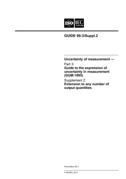
ISO IEC Guide 98-3-2008 Suppl.2-2011 测量不确定度第3部分:测量不确定度表达指南 (GUM:1995) 补充 2:扩展到任意数量的输出量VIP免费
 2024-09-15 155
 -
ISO 4413-2010 液压流体动力-系统及其元件的一般规则和安全要求VIP免费
 2025-02-07 147
 -
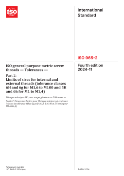
ISO 965-2-2024 通用公制螺纹 公差 第2部分:内螺纹和外螺纹尺寸极限VIP免费
 2025-03-20 283
 -
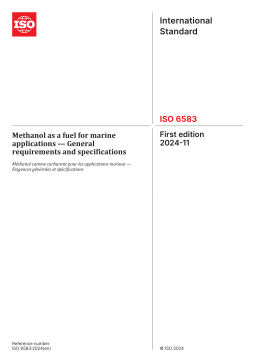
ISO 6583-2024 甲醇作为船用燃料 一般要求和规范VIP免费
 2025-04-02 236
 -
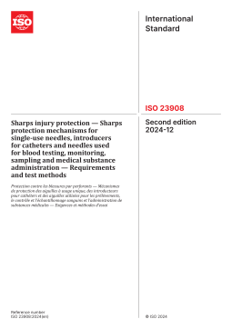
ISO 23908-2024 锐器伤害防护 用于血液测试、监测、取样和医疗物质给药的一次性针头、导管引入器和针头的锐器防护机构 要求和试验方法VIP免费
 2025-04-16 152
 -
ISO 14119-2024 机械安全——与防护装置相关的联锁装置——设计和选择原则VIP免费
 2025-04-21 170
 -
ISO 6028-2023 医疗机构管理 流行病应对 自我症状检查应用程序的功能要求VIP免费
 2025-05-18 197
 -
ISO 12233-2024 数字照相机——分辨率和空间频率响应VIP专免
 2025-06-22 200
 -
ISO 14001-2026 环境管理体系 要求和使用指南 高清英文版VIP免费
 2026-04-20 999+
作者:那山那人那狗
分类:国外协会
价格:18星币
属性:12 页
大小:724.48KB
格式:PDF
时间:2026-04-12
相关内容
-
ISO IEC 19583-27-2025 信息技术 元数据概念与使用 第27部分:可计算数据注册元模型与高通量测序生物信息学分析之间的映射
分类:国际标准
时间:2026-09-10
标签:ISO
格式:PDF
价格:26 星币
-
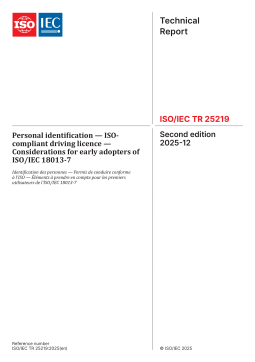
ISO IEC TR 25219-2025 个人识别 — ISO合规驾驶执照 — ISOIEC 18013-7早期采用者需考虑的事项
分类:国际标准
时间:2026-09-10
标签:ISO
格式:PDF
价格:26 星币
-
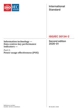
ISO IEC 30134-2-2026 信息技术 — 数据中心关键性能指标 — 第2部分:电能使用效率(PUE)
分类:国际标准
时间:2026-09-10
标签:ISO
格式:PDF
价格:26 星币
-

ISO IEC 30108-1-2026 生物测定 身份属性验证服务 第1部分IAVS服务
分类:国际标准
时间:2026-09-10
标签:ISO
格式:PDF
价格:26 星币
-
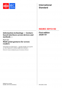
ISO IEC 30113-62-2026 信息技术 跨设备和方法的基于手势的界面 第62部分屏幕阅读器的多点手势
分类:国际标准
时间:2026-09-10
标签:ISO
格式:PDF
价格:26 星币


