
NFPA 20-2019 Handbook

VIP专享

Sixth Edition
Edited by
Chad R.W. Duy, P.E.
Senior Fire Protection Engineer, NFPA
Janna E. Shapiro
Fire Protection Engineer, NFPA
With the complete text of the following:
2019 edition of NFPA® 20, Standard for the Installation of Stationary Pumps for Fire Protection
2016 edition of NFPA® 14, Standard for the Installation of Standpipe and Hose Systems
2019 edition of NFPA® 291, Recommended Practice for Fire Flow Testing and Marking of Hydrants
2019 edition of NFPA® 24, Standard for the Installation of Private Fire Service Mains and Their Appurtenances
Stationary Fire Pumps and
Standpipe Systems Handbook
NATIONAL FIRE PROTECTION ASSOCIATION
The leading information and knowledge resource on fire, electrical and related hazards
BK-NFPA-20HB19-180214-FM.indd 1 08/11/18 12:07 PM
Copyright 2018 National Fire Protection Association (NFPA®). Licensed, by agreement, for individual use and download on 12/18/2018 to New Haven University Of. No other reproduction or transmission in any form permitted
without written permission of NFPA®. For inquiries or to report unauthorized use, contact licensing@nfpa.org. This NFCSS All Access subscription expires on September 30, 2019.
{7d1cf25d-f130-43e0-8b7f-041dc4ddd530}

Find
To nd a word or term in the PDF:
1. Select Find under the Edit menu or use the keyboard shortcut: CTRL + F for PC; COMMAND + F for Mac.
2. Type a word or term in the Find box. To specify Whole words only or Case-sensitive, use the drop-down arrow
to the right of the Find box and toggle these criteria on or o.
The found term will be highlighted in the text. To go to other occurrences of the term, use the previous and next
buttons that appear beside the Find box.
Advanced Search
Use the drop-down arrow to the right of the Find box and select Open Full Search. Additional search options are
available by selecting Show More Options at the bottom of the pane. Options in the advanced search window
include matching the exact word or phrase, matching only some of the words, and stemming (see below).
Stemming nds words that contain part (the stem) of a specied search word. For example, a search for
the word opening would nd instances of open, opened, opens, and openly. Wildcard characters (* or ?)
are not permitted in stemming searches. Stemming isn’t available if either Whole words only or
Case-sensitive is selected.
Links
Links to other sections of the document are colored red. When you click on a link and are directed to another
page, use the following keyboard shortcut to return to the original page: ALT + <left arrow> for PC;
COMMAND + <left arrow> for Mac.
PDF Navigation Tips
Copyright 2018 National Fire Protection Association (NFPA®). Licensed, by agreement, for individual use and download on 12/18/2018 to New Haven University Of. No other reproduction or transmission in any form permitted
without written permission of NFPA®. For inquiries or to report unauthorized use, contact licensing@nfpa.org. This NFCSS All Access subscription expires on September 30, 2019.
{7d1cf25d-f130-43e0-8b7f-041dc4ddd530}

The 2019 edition of the Stationary Fire Pumps and Standpipe Systems Handbook contains the complete
mandatory text of the 2019 edition of NFPA 20, Standard for the Installation of Stationary Pumps for Fire
Protection, and the 2016 edition of NFPA 14, Standard for the Installation of Standpipe and Hose Systems,
as well as expert commentary to assist users in their understanding and application of the standards.
In addition to the commentary text, this edition of the handbook also offers a number of helpful fea-
tures, which are described below.
2019 Stationary Fire Pumps and Standpipe Systems Handbook
312 Part I•NFPA 20•Chapter 10 Electric-Drive Controllers and Accessories
10.4 Components
10.4.1* Voltage Surge Arrester.
A.10.4.1 Operation of the surge arrester should not cause either the isolating switch or the cir-
cuit breaker to open. Arresters in ANSI/IEEE C62.11, IEEE Standard for Metal-Oxide Surge
Arresters for Alternating Current Power Circuits (>1 kV), are normally zinc-oxide without gaps.
The “gaps” referred to in A.10.4.1 are common when using the silicon-carbide (Si-C) types of surge
arresters referred to in 10.4.1.1. A surge voltage of sufficient magnitude arcs across the gap and the Si-C
semiconductor element absorbs the surge energy. Once the voltage decays sufficiently or at the next
zero crossing of the current, the arc extinguishes and prevents any further leakage or follow-on current.
This allows the Si-C element to cool down and be ready for the next surge, spike, or transient event.
10.4.1.1 Unless the requirements of 10.4.1.3 or 10.4.1.4 are met, a voltage surge arrester
complying with ANSI/IEEE C62.1, IEEE Standard for Gapped Silicon-Carbide Surge Arrest-
ers for AC Power Circuits, or ANSI/IEEE C62.11, IEEE Standard for Metal-Oxide Surge
Arresters for Alternating Current Power Circuits (>1 kV), shall be installed from each phase
to ground. (See 10.3.3.3.)
Surge arresters are provided in controllers to prevent power line surges from damaging components in
the controller and/or rendering them inoperable. Typical failures due to a power line surge are burnouts
of indicating lamps and dielectric breakdowns of the magnetic contactor holding coil.
10.4.1.2 The surge arrester shall be rated to suppress voltage surges above line voltage.
Even when the surge arrester is rated above line voltage as required by this section, there will be some
amount of increase of the voltage during a surge; no arrester can perfectly clamp excess voltage. How-
ever, properly rated devices should limit damage to the equipment. Some controller designs have a
high “voltage withstand” capability to provide the most reliability against surges.
10.4.1.3 The requirements of 10.4.1.1 and 10.4.1.2 shall not apply to controllers rated in
excess of 600 V. (See Section 10.6.)
The typical voltages involved are 2300 V ac or higher. These controllers are required to meet a minimum
basic insulation level (BIL) so that they are immune to normal surges, switching spikes, and transients.
10.4.1.4 The requirements of 10.4.1.1 and 10.4.1.2 shall not apply where the controller can
withstand without damage a 10 kV impulse in accordance with ANSI/IEEE C62.41, IEEE
Recommended Practice for Surge Voltages in Low-Voltage AC Power Circuits, or where the
controller is listed to withstand surges and impulses in accordance with ANSI/UL 1449, Stan-
dard for Surge Protective Devices.
The reference to ANSI/UL 1449, Standard for Surge Protective Devices, was added as an alternative to the
10 kV (10,000 volt) impulse test provision because it is an ANSI standard and readily available to test to
at the approval agencies.
.
Δ
BK-NFPA-20HB19-180214-Part1_Chp10.indd 312 02/11/18 6:12 PM
Commentary text, which is printed in black
and shaded in yellow, is intended to assist
users in understanding and applying NFPA
20 and NFPA 14.
Mandatory text and nonmandatory annex
text from the standards are printed in
black with shading to indicate where text
has changed from the previous edition of
the standard.
Features of the Stationary Fire Pumps and
Standpipe Systems Handbook, 2019 Edition
Section 4.20 • Relief Valves for Centrifugal Pumps 117
Stationary Fire Pumps and Standpipe Systems Handbook 2019
valve is required by the standard to be installed is when the diesel engine is turning faster
than normal, and since this is a relatively rare event, it is permitted for the discharge from
the pressure relief valve to be piped back to the suction side of the pump.
4.20.1.1* Pressure relief valves shall be used only where specifically permitted by this
standard.
The use of a main pressure relief valve to trim excess pressure is considered to
be poor design and should be avoided. Several methods are available to cope
with excessive pressures, such as the following:
1. A break tank
2. A variable speed pressure-limiting control device (see 11.2.4.3)
3. Other pressure-regulating devices downstream of the fire pump discharge
control valve
A.4.20.1.1 In situations where the required system pressure is close
to the pressure rating of the system components and the water supply
pressure varies signicantly over time, to eliminate system overpres-
surization, it might be necessary to use one of the following:
(1) A tank between the water supply and the pump suction, in lieu
of directly connecting to the water supply piping
(2) A variable speed pressure limiting control device
4.20.1.2 Where a diesel engine re pump is installed and where a total of 121 percent of
the net rated shutoff (churn) pressure plus the maximum static suction pressure, adjusted for
elevation, exceeds the pressure for which the system components are rated, a pressure relief
valve shall be installed.
Pumps that create pressures less than the pressure rating of the fire protection system compo-
nents [typically 175 psi (12.1 bar)] at 110 percent of rated speed do not need a pressure relief valve.
The sample calculation that follows illustrates the procedure used to determine if a pressure relief
valve is needed.
The plans for a diesel engine–driven centrifugal pump
do not show the installation of a pressure relief valve. Is
this omission permitted?
ANSWER: Yes, this is acceptable in some installations. The
pressure relief valve requirement on diesel engine–driven
pumps is intended to prevent the piping from overpressur-
ization if the fire pump malfunctions and runs at a higher
speed than anticipated. If 121 percent of the pump’s churn
pressure is added to the maximum static pressure of the
water supply, and the total does not exceed the maximum
working pressure of the system components, a pressure
relief valve is not required.
ASK THE AHJ
?
FAQ
Does NFPA 20 permit the installation of main pressure relief valves in electric fire pump systems?
No section in this standard specifically permits the use of a main pressure relief valve on an electric fire
pump, except where a variable speed driver is used. Variable speed drivers are required to default to con-
stant rated speed operation in the event the variable speed driver fails. If operating at constant rated speed
can result in system overpressurization, a pressure relief valve is required. The pressure relief valve setting
must be above the set pressure of the variable speed driver.
BK-NFPA-20HB19-180214-Part1_Chp04.indd 117 11/3/18 1:58 PM
Frequently asked questions (FAQs)
are based on the most commonly
asked questions of the NFPA 20 and
NFPA 14 staff.
Ask the AHJ questions offer
snapshots of typical situations faced
by authorities having jurisdiction.
2019 Stationary Fire Pumps and Standpipe Systems Handbook
118 Part I•NFPA 20•Chapter 4 General Requirements
Prior to the 1996 edition, NFPA 20 required the installation of pressure relief valves for all diesel engine
fire pumps. This requirement was based on the assumption that, if engines ran too fast (a condition
known as overspeed), the fire protection system would be exposed to pressures in excess of the
pressure ratings of the system components. Because an overspeed shutdown device is required (see
11.2.4.4.1), the technical committee believes that a pressure relief valve is not needed on all diesel fire
pump installations.
A re pump rated for 1500 gpm (5677 L/min) and 100 psi (6.9 bar) at 1750 rpm has a shuto pressure
of 120 psi (8.3 bar). The shuto pressure produces 145 psi (10 bar) at 110 percent of rated speed. If a
maximum of 45 psi (3.1 bar) static pressure is available from the city water supply, the total pressure
when the pump is running at churn at 110 percent of rated speed is 190 psi (13.1bar).
Pressure increase at 110 percent of rated speed = 110%2 = 121%
120 psi (8.3 bar) × 1.21 = 145 psi (10 bar)
145 psi + 45 psi (10 bar + 3.1 bar) = 190 psi (13.1 bar)
In this case, a pressure relief valve (see Exhibit I.4.27) is needed if the re protection system com-
ponents are rated at 175 psi (12.1 bar). A pressure relief valve is not required if the re protection system
components are rated for 200 psi (13.8 bar) or higher.
CALCULATION EXAMPLE
EXHIBIT I.4.27 Pressure Relief
Valve with Waste Cone. (Courtesy
of JENSEN HUGHES, Inc.) Pressure relief valve
Discharge site cone
4.20.1.3 Where an electric variable speed pump or a diesel pressure limiting driver is
installed, and the maximum total discharge head adjusted for elevation with the pump operat-
ing at shutoff and rated speed exceeds the pressure rating of the system components, a pres-
sure relief valve shall be installed.
BK-NFPA-20HB19-180214-Part1_Chp04.indd 118 11/3/18 1:58 PM
Calculation Examples
illustrate important equations
and formulas.
Interactive PDF versions of the forms
featured in Part IV, Supplement 3 are
also available as “eForms” at
nfpa.org/20.
2019 Stationary Fire Pumps and Standpipe Systems Handbook
246 Part I•NFPA 20•Chapter 8 Positive Displacement Pumps
8.6.2.3 Bearings shall be in accordance with AGMA standards and applied for an L10 life of
15,000 hours.
8.6.2.4 For drive systems that include a gear case, the pump manufacturer shall provide a
complete mass elastic system torsional analysis to ensure there are no damaging stresses or
critical speeds within 25 percent above and below the operating speed of the pump(s) and
driver.
8.6.2.4.1 For variable speed drives, the analysis of 8.6.2.4 shall include all speeds down to 25
percent below the lowest operating speed obtainable with the variable speed drive.
8.6.3 Common Drivers.
8.6.3.1 A single driver shall be permitted to drive more than one positive displacement pump.
Paragraph 8.6.3.1 overrides the requirement in 4.7.4 and permits one motor/engine to drive multiple
pumps. The flow demands of a water mist fire protection system, combined with the low operat-
ing flow range of a positive displacement pump, commonly require that more than one pump be
driven off the same motor/engine driver. Manufacturers typically supply this arrangement in a preas-
sembled unit.
CLOSER LOOK
Torsional Vibration
Torsional vibration is the angular speed fluctuation of a rotating power train system. The fluctuations
are in response to torque pulsation from the driver, such as a diesel engine, or the load, such as a
positive displacement piston pump. Driveline components have inertia (mass) and store energy like
a spring when they twist (like elastic). When these components are assembled into a driveline sys-
tem, a unique “mass elastic system” is created that has unique resonant behavior. Resonance is also
referred to as natural frequency.
Think of resonant response as that of a tuning fork or wine glass to a vibration input. These simple
examples have a unique natural frequency which, when excited by a forcing function at that same
frequency, will generate high levels of vibration response. This can lead to damage or failure, such
as the shattering of the wine glass. The driveline will exhibit similar resonant behavior and must be
carefully designed so that frequency of the torque pulsations produced by the driver do not excite
any of the natural frequencies of the system when operating at any normal operating speed. The
rotational speed at which the pulsation frequency coincides with a natural frequency is referred to
a critical speed. Damage or failure to the driveline may result if the system is operating too close to a
critical speed.
“A complete mass elastic system torsional analysis” is an analytical computation that predicts the
dynamic response of a rotating power train system; it predicts critical speeds. Often referred to as a
torsional vibration analysis (TVA), it is exclusively concerned with the rotating degree of freedom and
disregards any lateral vibration (vibrations felt by the hand) or shaft whirl that may be present. This
is a tool the pump system designer can use to avoid designing a driveline that will run near a critical
speed. The mass elastic system model typically comprises lumped inertias connected by torsional
springs and damping elements. The data required to assemble the model is obtained from compo-
nent suppliers, measured in a lab, or estimated using an analytical solid model or finite element (FE)
model. The accuracy of the predicted response relies on the accuracy of the input data; care should
be taken to obtain the most accurate input information possible. Exhibit I.8.8 provides images of
damage that resulted from the rotating system being torsionally incompatible.
BK-NFPA-20HB19-180214-Part1_Chp08.indd 246 11/3/18 1:54 PM
Section 4.7 • Pumps, Drivers, and Controllers 75
Stationary Fire Pumps and Standpipe Systems Handbook 2019
4.7.7.2* Pressure relief valves and pressure-regulating devices in the re pump installation
shall not be used as a means to meet the requirements of 4.7.7.1.
The use of pressure relief valves is limited in this standard to the following situations:
• Constant speed diesel engine drivers where pressures developed can exceed the pressure rating
of system components if a 10 percent overspeed condition occurs.
• Variable speed drivers where pressures developed can exceed the pressure rating of system com-
ponents if a failure causes the driver to revert to rated speed.
A pump should never be deliberately oversized so that a pressure-regulating device is needed.
Pressure relief valves are maintenance intensive and should be incorporated into the design of a fire
pump system only when necessary and allowed by this standard. Pressure-reducing valves are not per-
mitted to be installed in the fire pump system piping. Where pump discharge pressures exceed 175
psi (12.1 bar), flanged cast-iron valves and fittings between the fire pump discharge flange and the
discharge isolation valve must be of extra heavy pattern. It is not the intent of 4.7.7.2 to limit the use
of pressure-reducing valves or pressure-regulating valves downstream of the discharge isolation valve.
The use of pressure-regulating valves downstream of the discharge isolation valve is covered in other
standards. In many cases, high-pressure output is needed to meet the design requirements of systems
installed in high-rise buildings and in standpipe systems in particular.
A.4.7.7.2 It is not the intent of this subsection to restrict the use of pressure-reducing valves
downstream of the discharge isolation valve for the purpose of meeting the requirements
of 4.7.7.
4.7.7.3 Variable Speed Pump.
4.7.7.3.1 Variable speed pumps, as dened in this standard, shall be acceptable to limit sys-
tem pressure.
Variable speed pumps control system pressure by changing the pump speed to prevent overpressur-
ization of the fire protection system. Using a variable speed pump can eliminate the need to use pres-
sure-regulating devices, such as pressure-reducing valves, in some system designs. A variable speed
pump can be used when high flow and high pressure are needed but, due to the nature of fire pump
SEE MORE
For more information on pres-
sure control, see the feature
Controlling Excess Fire Pump
Pressures at the end of this
chapter.
DESIGN ALERT
EXHIBIT I.4.7 Check Valve
Listed for 300 psi (20.7 bar).
(Courtesy of JENSEN HUGHES,
Inc.)
BK-NFPA-20HB19-180214-Part1_Chp04.indd 75 11/3/18 1:56 PM
See More boxes indicate where
additional information can be
found in other sections of the
handbook.
Design Alert icons in the
margins alert users to points
of special interest.
Closer Look features provide
further information on select-
ed topics from the standards.
Copyright 2018 National Fire Protection Association (NFPA®). Licensed, by agreement, for individual use and download on 12/18/2018 to New Haven University Of. No other reproduction or transmission in any form permitted
without written permission of NFPA®. For inquiries or to report unauthorized use, contact licensing@nfpa.org. This NFCSS All Access subscription expires on September 30, 2019.
{7d1cf25d-f130-43e0-8b7f-041dc4ddd530}

摘要:
展开>>
收起<<
The NFPA 20-2019 Handbook provides comprehensive guidance on the installation, maintenance, and testing of fire pumps and related equipment, serving as an essential resource for engineers, contractors, and facility managers. This edition includes the
声明:本文档系会员上传,若文档所含内容侵犯了您的版权或隐私,请立即通知,我们立即给予侵权申诉删除!
相关推荐
-
ISO TR 25901-1-2016 焊接及相关工艺-词汇第1部分:通用术语VIP免费

 2024-09-13 166
 -
ISO IEC Guide 98-3-2008 Suppl.2-2011 测量不确定度第3部分:测量不确定度表达指南 (GUM:1995) 补充 2:扩展到任意数量的输出量VIP免费
 2024-09-15 155
 -
ISO 4413-2010 液压流体动力-系统及其元件的一般规则和安全要求VIP免费
 2025-02-07 147
 -
ISO 965-2-2024 通用公制螺纹 公差 第2部分:内螺纹和外螺纹尺寸极限VIP免费
 2025-03-20 283
 -
ISO 6583-2024 甲醇作为船用燃料 一般要求和规范VIP免费
 2025-04-02 236
 -
ISO 23908-2024 锐器伤害防护 用于血液测试、监测、取样和医疗物质给药的一次性针头、导管引入器和针头的锐器防护机构 要求和试验方法VIP免费
 2025-04-16 152
 -
ISO 14119-2024 机械安全——与防护装置相关的联锁装置——设计和选择原则VIP免费
 2025-04-21 170
 -
ISO 6028-2023 医疗机构管理 流行病应对 自我症状检查应用程序的功能要求VIP免费
 2025-05-18 197
 -
ISO 12233-2024 数字照相机——分辨率和空间频率响应VIP专免
 2025-06-22 200
 -
ISO 14001-2026 环境管理体系 要求和使用指南 高清英文版VIP免费
 2026-04-20 999+
作者:阿拉丁
分类:国外协会
价格:18星币
属性:1043 页
大小:108.44MB
格式:PDF
时间:2024-09-16
相关内容
-

ISO IEC 19583-27-2025 信息技术 元数据概念与使用 第27部分:可计算数据注册元模型与高通量测序生物信息学分析之间的映射
分类:国际标准
时间:2026-09-10
标签:ISO
格式:PDF
价格:26 星币
-
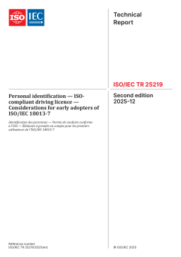
ISO IEC TR 25219-2025 个人识别 — ISO合规驾驶执照 — ISOIEC 18013-7早期采用者需考虑的事项
分类:国际标准
时间:2026-09-10
标签:ISO
格式:PDF
价格:26 星币
-
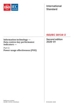
ISO IEC 30134-2-2026 信息技术 — 数据中心关键性能指标 — 第2部分:电能使用效率(PUE)
分类:国际标准
时间:2026-09-10
标签:ISO
格式:PDF
价格:26 星币
-

ISO IEC 30108-1-2026 生物测定 身份属性验证服务 第1部分IAVS服务
分类:国际标准
时间:2026-09-10
标签:ISO
格式:PDF
价格:26 星币
-
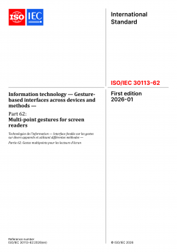
ISO IEC 30113-62-2026 信息技术 跨设备和方法的基于手势的界面 第62部分屏幕阅读器的多点手势
分类:国际标准
时间:2026-09-10
标签:ISO
格式:PDF
价格:26 星币


