
ASTM A333 - A 333M - 24 低温用无缝与焊接钢管规格

VIP免费

Designation: A333/A333M −24
Standard Specification for
Seamless and Welded Steel Pipe for Low-Temperature
Service and Other Applications with Required Notch
Toughness
1
This standard is issued under the fixed designation A333/A333M; the number immediately following the designation indicates the year
of original adoption or, in the case of revision, the year of last revision. A number in parentheses indicates the year of last reapproval.
A superscript epsilon (´) indicates an editorial change since the last revision or reapproval.
1. Scope*
1.1 This specification
2
covers nominal (average) wall seam-
less and welded carbon and alloy steel pipe intended for use at
low temperatures and in other applications requiring notch
toughness. Several grades of ferritic steel are included as listed
in Table 1. Some product sizes may not be available under this
specification because heavier wall thicknesses have an adverse
effect on impact properties.
1.2 The values stated in either SI units or inch-pound units
are to be regarded separately as standard. Within the text, the
SI units are shown in brackets. The values stated in each
system may not be exact equivalents; therefore, each system
shall be used independently of the other. Combining values
from the two systems may result in non-conformance with the
standard. The inch-pound units shall apply unless the “M”
designation of this specification is specified in the order.
NOTE 1—The dimensionless designator NPS (nominal pipe size) has
been substituted in this standard for such traditional terms as “nominal
diameter,” “size,” and “nominal size.”
1.3 This international standard was developed in accor-
dance with internationally recognized principles on standard-
ization established in the Decision on Principles for the
Development of International Standards, Guides and Recom-
mendations issued by the World Trade Organization Technical
Barriers to Trade (TBT) Committee.
2. Referenced Documents
2.1 ASTM Standards:
3
A370 Test Methods and Definitions for Mechanical Testing
of Steel Products
A999/A999M Specification for General Requirements for
Alloy and Stainless Steel Pipe
A671/A671M Specification for Electric-Fusion-Welded
Steel Pipe for Atmospheric and Lower Temperatures
E23 Test Methods for Notched Bar Impact Testing of Me-
tallic Materials
E165/E165M Practice for Liquid Penetrant Testing for Gen-
eral Industry
E709 Guide for Magnetic Particle Testing
2.2 ASME Boiler and Pressure Vessel Code:
4
Section VIII
Section IX
3. Ordering Information
3.1 Orders for material under this specification should
include the following, as required, to describe the material
adequately:
3.1.1 Quantity (feet, centimetres, or number of lengths),
3.1.2 Name of material (seamless or welded pipe),
3.1.3 Grade (Table 1),
3.1.4 Size (NPS or outside diameter and schedule number of
average wall thickness),
3.1.5 Lengths (specific or random) (Section 9), (see the
Permissible Variations in Length section of Specification
A999/A999M),
3.1.6 End finish (see the Ends section of Specification
A999/A999M),
3.1.7 Optional requirements, (see the Heat Analysis require-
ment in the Chemical Composition section of A999/A999M,
the Repair by Welding section, and the section on Nondestruc-
tive Test Requirements),
3.1.8 Test report required, (see the Certification section of
Specification A999/A999M),
3.1.9 Specification designation, and
3.1.10 Special requirements or exceptions to this specifica-
tion.
1
This specification is under the jurisdiction of ASTM Committee A01 on Steel,
Stainless Steel and Related Alloys and is the direct responsibility of Subcommittee
A01.10 on Stainless and Alloy Steel Tubular Products.
Current edition approved April 1, 2024. Published April 2024. Originally
approved in 1950. Last previous edition approved in 2018 as A333/A333M – 18.
DOI: 10.1520/A0333_A0333M-24.
2
For ASME Boiler and Pressure Vessel Code applications see related Specifi-
cation SA-333 in Section II of that Code.
3
For referenced ASTM standards, visit the ASTM website, www.astm.org, or
contact ASTM Customer Service at service@astm.org. For Annual Book of ASTM
Standards volume information, refer to the standard’s Document Summary page on
the ASTM website.
4
Available from American Society of Mechanical Engineers (ASME), ASME
International Headquarters, Two Park Ave., New York, NY 10016-5990, http://
www.asme.org.
*A Summary of Changes section appears at the end of this standard
Copyright © ASTM International, 100 Barr Harbor Drive, PO Box C700, West Conshohocken, PA 19428-2959. United States
This international standard was developed in accordance with internationally recognized principles on standardization established in the Decision on Principles for the
Development of International Standards, Guides and Recommendations issued by the World Trade Organization Technical Barriers to Trade (TBT) Committee.
1

3.1.11 Supplementary requirements, if any (subsize impact
specimens, pipe for hydrofluoric acid alkylation service).
4. Materials and Manufacture
4.1 Manufacture—Except as provided in paragraph 4.2, the
pipe shall be made by the seamless or welding process with the
addition of no filler metal in the welding operation. Grade 4
shall be made by the seamless process.
NOTE 2—For electric-fusion-welded pipe, with filler metal added,
fabricated of pressure vessel quality plates, see Specification A671/
A671M.
4.2 Grade 11 pipe may be produced by welding with or
without the addition of filler metal. The following requirements
shall apply for Grade 11 welded with the addition of filler
metal.
4.2.1 The joints shall be full-penetration, full fusion double-
welded or single-welded butt joints employing fusion welding
processes as defined in “Definitions,” ASME Boiler and
Pressure Vessel Code, Section IX. This specification makes no
provision for any difference in weld quality requirements
regardless of the weld joint type employed (single or double) in
making the weld. Where backing strips are employed, the ring
or strip material shall be the same as the plate being joined.
Backing rings or strips shall be completely removed after
welding, prior to any required radiography, and the exposed
weld surface shall be examined visually for conformance to the
requirements of 4.2.2. Welds made by procedures employing
backing strips or rings which remain in place are prohibited.
Welding procedures and welding operators shall be qualified in
accordance with ASME Boiler and Pressure Vessel Code,
Section IX.
4.2.2 The weld surface on either side of the weld may be
flush with the base plate or may have a reasonably uniform
crown, not to exceed
1
⁄
8
in. [3 mm]. Any weld reinforcement
may be removed at the manufacturer’s option or by agreement
between the manufacturer and purchaser. The contour of the
reinforcement shall be reasonably smooth and free from
irregularities. The deposited metal shall be fused uniformly
into the plate surface. No concavity of contour is permitted
unless the resulting thickness of weld metal is equal to or
greater than the minimum thickness of the adjacent base metal.
4.2.3 Radiographic Examination—All welded joints shall
be fully radiographed in accordance with the requirements of
the ASME Boiler and Pressure Vessel Code, Section VIII,
Division 1, latest edition, paragraph UW-51.
4.2.3.1 As an alternative, the welded joints may be ultra-
sonically examined in accordance with Appendix 12 of the
ASME Boiler and Pressure Vessel Code, Section VIII, Division
1.
4.2.4 Repair Welding—Weld metal defects shall be repaired
by removal to sound metal and repair welding if approved by
the purchaser.
4.2.4.1 The repair shall be blended smoothly into the
surrounding base metal surface and examined by the magnetic
particle examination in accordance with Practice E709, or by
the liquid penetrant method in accordance with Practice
E165/E165M.
4.2.4.2 Each repair weld of a cavity where the cavity, before
repair welding, has a depth exceeding the lesser of
3
⁄
8
in. [9.5
mm] or 10.5 % of the nominal thickness shall be radiographi-
cally examined as required for the original welds.
4.2.5 Transverse Tension Test—One test shall be made to
represent each lot (Note 3) of finished pipe. The test specimens
shall be taken across the welded joint. The tension test results
of the welded joints shall conform to the tensile properties for
Grade 11 in Table 2.
4.2.5.1 The test specimens shall be taken from the end of the
finished pipe. As an alternative, the tension test specimens may
be taken from a welded prolongation of the same material as
the pipe, which is attached to the end of the pipe and welded as
a prolongation of the pipe longitudinal seam.
4.2.5.2 The test specimens shall be in accordance with
Section IX, Part QW, paragraph QW-150 of the ASME Boiler
and Pressure Vessel Code and shall be one of the types shown
in QW-462.1 of that code. The tension test specimen may be
flattened cold before final machining to size.
TABLE 1 Chemical Requirements
B
Element Composition, %
Grade 1 Grade 3 Grade 4 Grade 6 Grade 7 Grade 8 Grade 9 Grade 10 Grade 11
Carbon, max 0.30 0.19 0.12 0.30 0.19 0.13 0.20 0.20 0.10
Manganese 0.40–1.06
A
0.31–0.64 0.50–1.05 0.29–1.06
A
0.90 max 0.90 max 0.40–1.06 1.15–1.50 0.60 max
Phosphorus,
max
0.025 0.025 0.025 0.025 0.025 0.025 0.025 0.035 0.025
Sulfur, max 0.025 0.025 0.025 0.025 0.025 0.025 0.025 0.015 0.025
Silicon ... 0.18–0.37 0.08–0.37 0.10 min 0.13–0.32 0.13–0.32 ... 0.10–0.35 0.35 max
Nickel ... 3.18–3.82 0.47–0.98 0.40 max 2.03–2.57 8.40–9.60 1.60–2.24 0.25 max 35.0–37.0
Chromium ... ... 0.44–1.01 0.30 max ... ... ... 0.15 max 0.50 max
Copper ... ... 0.40–0.75 0.40 max ... ... 0.75–1.25 0.15 max ...
Aluminum ... ... 0.04–0.30 ... ... ... ... 0.06 max ...
Vanadium, max ... ... ... 0.08 ... ... ... 0.12 ...
Niobium
D
, max ... ... ... 0.02
C
... ... ... 0.05 ...
Molybdenum,
max
... ... ... 0.12 ... ... ... 0.05 0.50 max
Cobalt ... ... ... ... ... ... ... ... 0.50 max
A
For each reduction of 0.01 % carbon below 0.30 %, an increase of 0.05 % manganese above 1.06 % would be permitted to a maximum of 1.35 % manganese.
B
Where an ellipsis (...) appears in this table, there is no requirement and analysis for the element need not to be determined or reported.
C
By agreement between the manufacturer and the purchaser, the limit for niobium may be increased up to 0.05 % on heat analysis and 0.06 % on product analysis.
D
The terms Niobium (Nb) and Columbium (Cb) are alternate names for the same element.
A333/A333M − 24
2

4.2.6 Transverse Guided-Bend Weld Test—One transverse
guided bend test (two specimens) shall be made to represent
each lot (Note 3) of finished pipe.
4.2.6.1 The two bend test specimens shall be taken from the
weld at the end of the finished pipe. As an alternative, by
agreement between the purchaser and the manufacturer, the test
TABLE 2 Tensile Requirements
Grade 1 Grade 3 Grade 4 Grade 6 Grade 7 Grade 8 Grade 9 Grade 10 Grade 11
psi MPa psi MPa psi MPa psi MPa psi MPa psi MPa psi MPa psi MPa psi MPa
Tensile strength, min
Yield strength, min
55 000
30 000
380
205
65 000
35 000
450
240
60 000
35 000
415
240
60 000
35 000
415
240
65 000
35 000
450
240
100 000
75 000
690
515
63 000
46 000
435
315
80 000
65 000
550
450
65 000
35 000
450
240
Longi-
tudinal
Trans-
verse
Longi-
tudinal
Trans-
verse
Longi-
tudinal
Trans-
verse
Longi-
tudinal
Trans-
verse
Longi-
tudinal
Trans-
verse
Longi-
tudinal
Trans-
verse
Longi-
tudinal
Trans-
verse
Longi-
tudinal
Trans-
verse
Longi-
tudinal
Elongation in 2 in. or 50
mm, (or 4D), min, %:
Basic minimum
elongation for walls
5
⁄
16
in. [8 mm] and over in
thickness, strip tests,
and for all small sizes
tested in full section
35 25 30 20 30 16.5 30 16.5 30 22 22 ... 28 ... 22 ... 18
A
When standard round
2-in. or 50-mm gage
length or proportionally
smaller size test
specimen with the gage
length equal to 4D (4
times the diameter) is
used
28 20 22 14 22 12 22 12 22 14 16 ... ... ... 16 ... ...
For strip tests, a
deduction for each
1
⁄
32
in. [0.8 mm] decrease in
wall thickness below
5
⁄
16
in. [8 mm] from the
basic minimum
elongation of the
following percentage
1.75
B
1.25
B
1.50
B
1.00
B
1.50
B
1.00
B
1.50
B
1.00
B
1.50
B
1.00
B
1.25
B
... 1.50
B
... 1.25
B
... ...
Wall Thickness Elongation in 2 in. or 50 mm, min, %
C
Grade 1 Grade 3 Grade 4 Grade 6 Grade 7 Grade 8 Grade 9 Grade 10
in. mm Longi- Trans- Longi- Trans- Longi- Trans- Longi- Trans- Longi- Trans- Longi- Trans- Longi- Trans- Longi- Trans-
tudinal verse tudinal verse tudinal verse tudinal verse tudinal verse tudinal verse tudinal verse tudinal verse
5
⁄
16
(0.312) 8 35 25 30 20 30 16 30 16 30 22 22 ... 28 ... 22 ...
9
⁄
32
(0.281) 7.2 33 24 28 19 28 15 28 15 28 21 21 ... 26 ... 21 ...
1
⁄
4
(0.250) 6.4 32 23 27 18 27 15 27 15 27 20 20 ... 25 ... 20 ...
7
⁄
32
(0.219) 5.6 30 ... 26 ... 26 ... 26 ... 26 ... 18 ... 24 ... 18 ...
3
⁄
16
(0.188) 4.8 28 ... 24 ... 24 ... 24 ... 24 ... 17 ... 22 ... 17 ...
5
⁄
32
(0.156) 4 26 ... 22 ... 22 ... 22 ... 22 ... 16 ... 20 ... 16 ...
1
⁄
8
(0.125) 3.2 25 ... 21 ... 21 ... 21 ... 21 ... 15 ... 19 ... 15 ...
3
⁄
32
(0.094) 2.4 23 ... 20 ... 20 ... 20 ... 20 ... 13 ... 18 ... 13 ...
1
⁄
16
(0.062) 1.6 21 ... 18 ... 18 ... 18 ... 18 ... 12 ... 16 ... 12 ...
A
Elongation of Grade 11 is for all walls and small sizes tested in full section.
B
The following table gives the calculated minimum values.
C
Calculated elongation requirements shall be rounded to the nearest whole number.
Note—The preceding table gives the computed minimum elongation values for each
1
⁄
32
-in. [0.80-mm] decrease in wall thickness. Where the wall thickness lies between
two values shown above, the minimum elongation value is determined by the following equation:
Grade Direction of Test Equation
1 Longitudinal E = 56 t+ 17.50 [E= 2.19 t+ 17.50]
Transverse E = 40 t+ 12.50 [E= 1.56 t+ 12.50]
3 Longitudinal E = 48 t+ 15.00 [E= 1.87 t+ 15.00]
Transverse E = 32 t+ 10.00 [E= 1.25 t+ 10.00]
4 Longitudinal E = 48 t+ 15.00 [E= 1.87 t+ 15.00]
Transverse E = 32 t+ 6.50 [ E= 1.25 t+ 6.50]
6 Longitudinal E = 48 t+ 15.00 [E= 1.87 t+ 15.00]
Transverse E = 32 t+ 6.50 [ E= 1.25 t+ 6.50]
7 Longitudinal E = 48 t+ 15.00 [E= 1.87 t+ 15.00]
Transverse E = 32 t+ 11.00 [E= 1.25 t+ 11.00]
8 and 10 Longitudinal E = 40 t+ 9.50 [ E= 1.56 t+ 9.50]
9 Longitudinal E = 48 t+ 13.00 [E= 1.87 t+ 13.00]
where:
E= elongation in 2 in. or 50 mm, in %, and
t= actual thickness of specimen, in. [mm].
A333/A333M − 24
3

摘要:
展开>>
收起<<
ASTM A333/A333M-2024 Standard Specification for Seamless and Welded Steel Pipe for Low-emperature Service 低温用无缝与焊接钢管规格
声明:本文档系会员上传,若文档所含内容侵犯了您的版权或隐私,请立即通知,我们立即给予侵权申诉删除!
相关推荐
-
MIL-HDBK-217F NOTICE 2VIP免费
 2024-10-07 60
 -
MIL-HDBK-217FVIP专免
 2024-10-07 131
 -
MIL-STD-810G 环境工程考量与实验室测试VIP专免
 2024-10-07 259
 -
MIL-STD-883L-2019 Department Of Defense Test Method Standard MicrocircuitsVIP专免
 2024-10-07 156
 -
MIL STD-810H-2022 含Change 1 美军标环境可靠性试验标准VIP专享
 2025-01-19 364
 -
MIL-STD-810H-2019 美军标环境可靠性试验标准VIP专免
 2025-01-19 499
 -
MIL-P-642-2B免费
 2025-06-14 19
 -
MIL-P-24691-3 (1)免费
 2025-06-14 61
 -
MIL-STD-883J CHANGE 2VIP专免
 2025-06-15 84
 -
NSWC-11 美国海军表面作战中心 机械设备可靠性预计程序手册 Handbook of Reliability Prediction Procedures for Mechanical Equipment 2011VIP免费
 2025-08-22 252
作者:Carl
分类:国外协会
价格:16星币
属性:8 页
大小:249.83KB
格式:PDF
时间:2024-09-02
相关内容
-
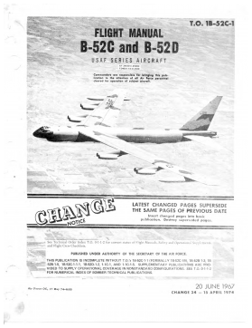
美国空军轰炸机 波音B-52C和B-52D系列飞机飞行手册 Boeing B-52C,B-52D Flight Manual (No. 1B-52C-1)
分类:国外协会
时间:2026-09-08
标签:飞行
格式:PDF
价格:45 星币
-
美军标 MIL-DTL-1189E(SH)+Amd 2-2026 青铜阀门与闸门规范
分类:国外协会
时间:2026-09-28
标签:阀门
格式:PDF
价格:26 星币
-
美军标 MIL-DTL-10382E-2026 食品处理机械和设备用喷涂凡士林防腐详细规范
分类:国外协会
时间:2026-09-28
标签:机械
格式:PDF
价格:26 星币
-
美军标 MIL-DTL-15382E-2026 耐火砖锚栓详细规格
分类:国外协会
时间:2026-09-28
标签:锚
格式:PDF
价格:26 星币
-
美军标 MIL-DTL-18480C-2026 煤焦油基溶剂沥青涂层化合物详细规范
分类:国外协会
时间:2026-09-28
标签:化合物
格式:PDF
价格:26 星币


